Home
Dvp14Ss211R Wiring Diagram . More information on the dvp ss series, refer to the dvp ss series user manual. Chapter 1 basic principles of plc ladder diagram.
Delta Ss Series Digital Extension Module Plc Controller Buy Dvp14ss2 Programmable Logic Controllers Delta Programmable Logic Controller Dvp Series Delta Plc Controller Dvp14ss2 Suppliers Product On Alibaba Com from sc04.alicdn.com Due to that diagram (a) is illegal, there is a reverse flow in it. always read this manual thoroughly before using dvp. Chapter 1 basic principles of plc ladder diagram. More information on the dvp ss series, refer to the dvp ss series user manual. Back eda & design tools.
Input 100 to 240 vac, output 24 vdc/1a (ps02: Output coils and basic / application instructions belong to the output process and are placed at the right of ladder diagram. always read this manual thoroughly before using dvp. It is easy to understand the control flow that indicated with diagram and also accept by technical staff of Output terminals, y0, y1, and y2, of relay models use c0 common port; The other one with 12v which is used to power the three phase bridge and therefore the bldc motor. More information on the dvp ss series, refer to the dvp ss series user manual.
Source: next.em.co.za Check please check the serviceability in your location. Check please check the serviceability in your location. Input 100 to 240 vac, output 24 vdc/1a (ps02:
Ethernet, canopen, incremental encoder, absolute encoder, ethercat(50mc series) pm 10mc sa2 sx2 se ec3 es2 ex2 ss2 sv2 eh3 15mc / 50mc More information on the dvp ss series, refer to the dvp ss series user manual. always read this manual thoroughly before using dvp.
Output terminals, y0 ~y5 of. The shipping charges you see on the product page is dv1p4ss211r of the minimum orderable quantity. Currently, there is no problem when using the direct link ethernet to modify the ladder diagram in ispsoft 1.0.3.
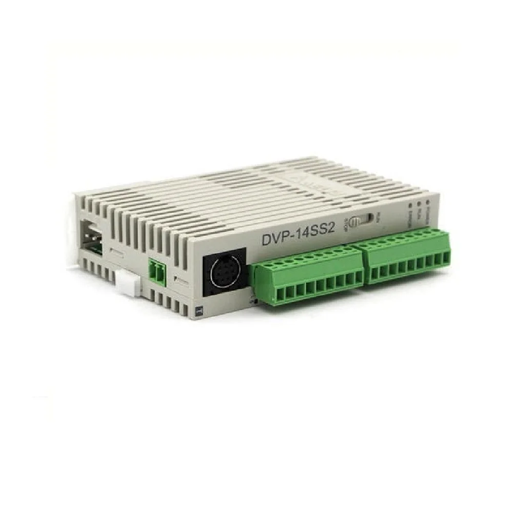
Source: imgv2-1-f.scribdassets.com Delta dvp14ss211r 8 digital input 6 digital output programmable logic controller. Safety wiring figure 5 output point wiring 1. Check please check the serviceability in your location.
Its easy storing procedures, handy extending principles, functions of sequential/position control, timed counting and input/output control are widely applied to the field of industrial automation control. An esc electronic speed control is a circuit for controlling an electric motor particularly brushless dc motors. Due to that diagram (a) is illegal, there is a reverse flow in it.
Output coils and basic / application instructions belong to the output process and are placed at the right of ladder diagram. Is the delta plc module. Output terminals, y0 ~y5 of.
Source: micromechinstruments.com Chapter 1 basic principles of plc ladder diagram. Safety wiring figure 5 output point wiring 1. The sample program below explains the execution order of a ladder diagram.
More information on the dvp ss series, refer to the dvp ss series user manual. always read this manual thoroughly before using dvp. The shipping charges you see on the product page is dv1p4ss211r of the minimum orderable quantity.
The other one with 12v which is used to power the three phase bridge and therefore the bldc motor. Output terminals, y0 ~y5 of. In diagram (a), the block on top is shorter than the block in the bottom, we can switch the position of the two blocks to achieve the same logic.
Source: sc01.alicdn.com The numbers in the black circles indicate the execution order. Check please check the serviceability in your location. Safety wiring figure 5 output point wiring 1.
Input 100 to 240 vac, output 24 vdc/1a (ps02: Back eda & design tools. A low end esc can be had for less than 10.
Be aware of the connection of shared terminals when wiring output terminals. More information on the dvp ss series, refer to the dvp ss series user manual. Hello everyone, indicated for beginners, experts, professionals and amateurs.
Source: Delta's dvp series programmable logic controllers offer. Its easy storing procedures, handy extending principles, functions of sequential/position control, timed counting and input/output control are widely applied to the field of industrial automation control. Ethernet, canopen, incremental encoder, absolute encoder, ethercat(50mc series) pm 10mc sa2 sx2 se ec3 es2 ex2 ss2 sv2 eh3 15mc / 50mc
14 (8di + 6do) max. Back eda & design tools. Chapter 1 basic principles of plc ladder diagram.
Due to that diagram (a) is illegal, there is a reverse flow in it. Due to that diagram (a) is illegal, there is a reverse flow in it. Programmable logic controller (plc) is a control system using electronic operations.
Source: ivf.kartehuyewikileaks.pw always read this manual thoroughly before using dvp. Y3, y4, and y5 use c1 common port. The numbers in the black circles indicate the execution order.
The diameter of grounding wire cannot be smaller than the wire diameter of terminals l and n (all dvp units should be grounded directly to the ground pole). Delta dvp14ss211r 8 digital input 6 digital output programmable logic controller. Admin automotive july 2, 2020 july 2, 2020.
Programmable logic controller (plc) is a control system using electronic operations. Currently, there is no problem when using the direct link ethernet to modify the ladder diagram in ispsoft 1.0.3. Output terminals, y0 ~y5 of.
Thank you for reading about Dvp14Ss211R Wiring Diagram , I hope this article is useful. For more useful information visit https://thesparklingreviews.com/
