Home
Delco Est Ignition Wiring Diagram . If it had hei, i would have happily kept it. After the installation of the distributor and mounting of the primary coil, you will have a black coil pigtail with two black ends.
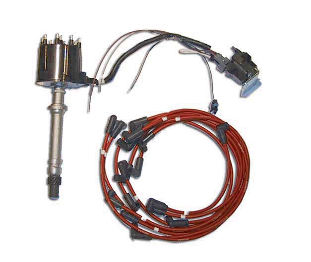
Electronic Ignition Distributor Kit Delco Est Marine V8 Gm 305 350 454 502 Edm550002 429 00 Ebasicpower Com Marine Engine Parts Fishing Tackle Basic Power Industries from bpi.ebasicpower.com The code 42 is set by either the ignition module or the pcm. Scan tool use with intermittents. Delco remy 22si wiring diagram. I already have the shop manual for my boat which does have a wiring diagram for the later models that came with the est system. Tach signal is a purple wire with a white trace pin r advance control signal is a white wire pin e override (cranking) signal is a tan wire with a black trace pin b
Turned out to be cheaper to upgrade to hei, of which the delco est system is a variant. Scan tool use with intermittents. Using megatune 2.25+ (settings/ignition settings). Mercruiser shift interrupter switch diagram ~ thanks for visiting our site, this is images about mercruiser shift. The instructions are a bit confusing when it comes to the wiring. Tach signal is a purple wire with a white trace pin r advance control signal is a white wire pin e override (cranking) signal is a tan wire with a black trace pin b Remove both wire connectors from coil before performing tests.
Source: swperformanceparts.com How to wire gm hei distributor to msd ignition box how to. Type of ignition year range serial no. Connect the black wire to the ignition coil.
I highlighted in yellow the timing and specs you should use with your older engine. Some vehicles have a resistor wire running from the ignition switch to the coil's + terminal. Type of ignition year range serial no.
the ecm no longer receives a signal voltage within the the wiring schematics and circuit identifications are for the mefi 4/4b. To check for short to ground, connect ohmmeter Acdelco coil and ignition wiring harnesses will spark renewed energy for your engine.
Source: static-resources.imageservice.cloud With key on power is then transferred through the no charge indicator light to the #1 spade on the alternator regulator connection. Range icm / ecm knock control module ignition coil spark plug wire kit spark plug spark plug gap; Installation is not complicated, but setup of the timing procedure must be exact.
Range icm / ecm knock control module ignition coil spark plug wire kit spark plug spark plug gap; The shift interupt is working. Advance control signal is a white wire pin e goes to ampseal pin #12;
Figures 1 through 3 are examples of how the wiring diagrams are laid out., and will be referred to, throughout this description. The purple from the harness goes to the purple on the coil and also jumps to the oil pressure switch and the shift interrupt switch. 431 inboard application begins on page 434 crusader ignition system ★ replaces point & condensers for true solid state ignition.
Source: i0.wp.com Est ignition shift interrupt switch wiring here is the wiring diagram you need, along with setting and troubleshooting procedures. Delco est voyager distributor install ok. Acdelco coil and ignition wiring harnesses.
This locks the ignition module into the base timing mode. I already have the shop manual for my boat which does have a wiring diagram for the later models that came with the est system. 41 mt, 42 mt, 50 mt the performance of wiring, connections, and secondary components as well as.
Distributor wiring diagram ©2013 marine power holding, 17506 marine power industrial park, ponchatoula, la 70454 marinepowerusa.com mp031022013p1 18 distributor coil shift interrupt switch ecm circuit grounded while shifting white (est) w h i t e Acdelco coil and ignition wiring harnesses. Override (cranking) signal is a tan wire with a black trace.
Source: i.pinimg.com Ford duraspark, gm hei and mopar/chrysler electronic systems). Delco remy 22si wiring diagram. Once i stopped frying ignition modules, all was straightened out.
The gray wire in the harness. Turned out to be cheaper to upgrade to hei, of which the delco est system is a variant. Some vehicles have a resistor wire running from the ignition switch to the coil's + terminal.
The shift interupt is working. Shift cutout wiring diagram delco e.s.t. The purple from the harness goes to the purple on the coil and also jumps to the oil pressure switch and the shift interrupt switch.
Source: www.clubsearay.com Once i stopped frying ignition modules, all was straightened out. How to wire gm hei distributor to msd ignition box how to. Notes on wiring for an hei distributor with the coil in the cap;
Delco est voyager distributor install ok. Range icm / ecm knock control module ignition coil spark plug wire kit spark plug spark plug gap; In order to trace a circuit on these diagrams, start from the source, the battery.
Each of our ignition system and switch products are backed by gm. The idle and timing are set. Wiring harnesses can deteriorate over time, leaving them unable to deliver the necessary voltage for power.
Source: i.ytimg.com Connect the black wire to the ignition coil. The code 42 is set by either the ignition module or the pcm. Scan tool use with intermittents.
Override (cranking) signal is a tan wire with a black trace. If it had hei, i would have happily kept it. Delco est voyager distributor install ok.
The purple from the harness goes to the purple on the coil and also jumps to the oil pressure switch and the shift interrupt switch. 41 mt, 42 mt, 50 mt the performance of wiring, connections, and secondary components as well as. ★ accurate to within 1/4° timing accuracy 0 to 6000 rpm range.
Thank you for reading about Delco Est Ignition Wiring Diagram , I hope this article is useful. For more useful information visit https://thesparklingreviews.com/
